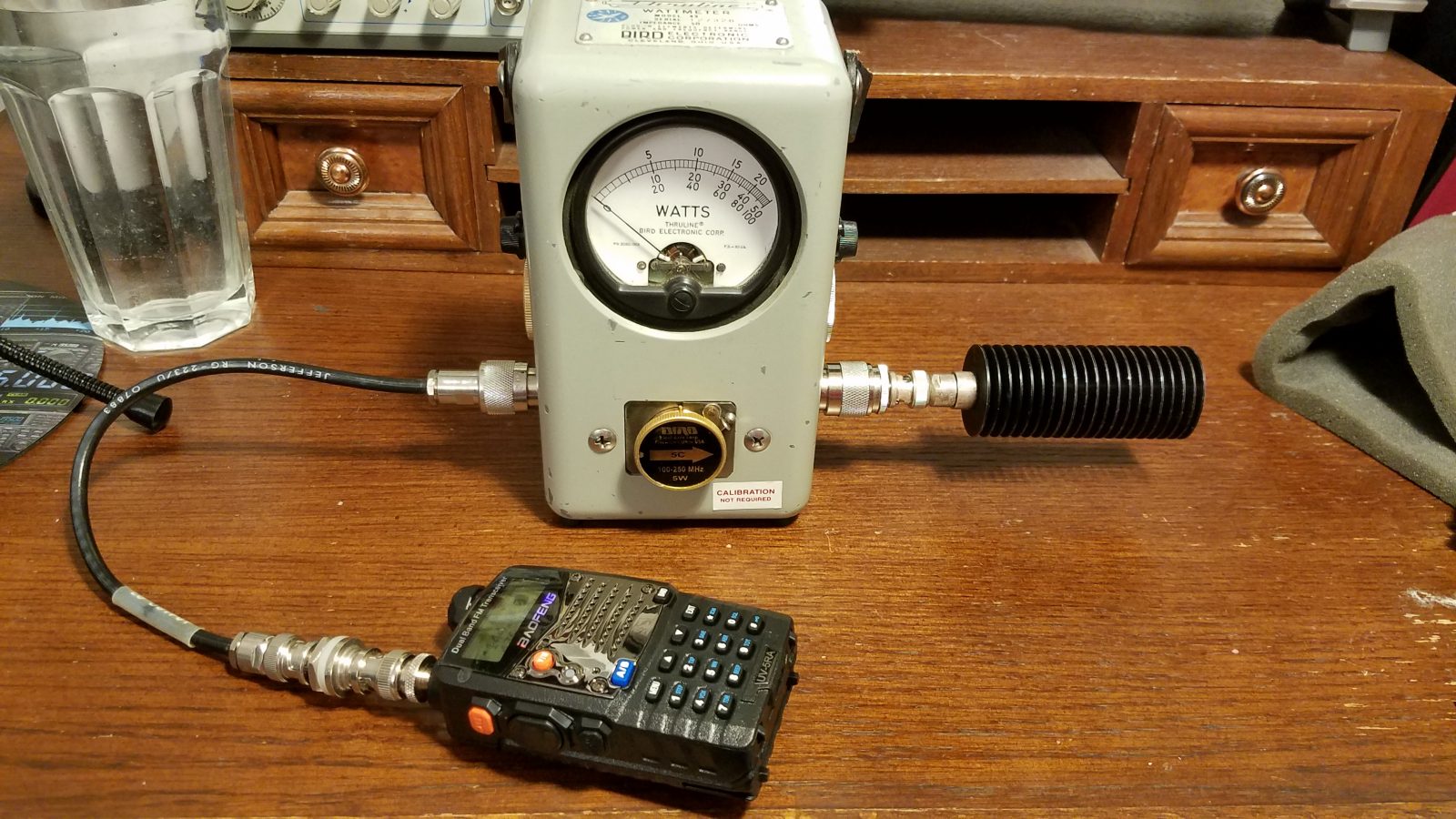
Note: This article is for educational and pre-compliance awareness only. It is not a substitute for certified laboratory testing, legal advice, or permission to transmit outside authorized frequencies. Always test into a proper 50-ohm dummy load, use enough attenuation to protect your equipment, and operate only where you are licensed or otherwise authorized.
Why Cheap Handheld Transceivers Deserve a Closer Look
Cheap handheld transceivers are the pocket calculators of the radio world: inexpensive, useful, surprisingly capable, and occasionally guilty of doing weird things when nobody is watching. For many amateur radio operators, emergency volunteers, experimenters, and budget-conscious hobbyists, low-cost handheld radios make VHF and UHF communication accessible. A $25 or $40 transceiver can open repeaters, monitor public-service channels where legal, and introduce beginners to RF basics without requiring a second mortgage.
But there is a technical catch hiding behind the cheerful orange backlight. A transmitter is supposed to produce energy mainly on the selected operating frequency. In real life, every transmitter also creates some unwanted energy outside the intended signal. These unwanted signals are called spurious emissions. They may appear as harmonics, mixer products, broadband noise, or little RF gremlins scattered across the spectrum. When they are weak enough, they are normal. When they are too strong, they can interfere with other services, violate radio rules, and make your bargain radio look less like a clever purchase and more like a noisy toaster with an antenna.
What Are Spurious Emissions?
Spurious emissions are unwanted RF signals produced by a transmitter outside the necessary bandwidth of the intended transmission. The most familiar type is the harmonic. If a handheld transceiver transmits on 146.520 MHz, its second harmonic appears around 293.040 MHz, and its third harmonic appears around 439.560 MHz. That third harmonic lands in a region many radio people recognize quickly, which is exactly why harmonic suppression matters.
Not every unwanted signal is a clean harmonic. Some spurs come from oscillator leakage, poor filtering, switching regulators, internal digital circuits, or mixing products created inside the radio. Cheap handheld transceivers often use highly integrated RF chips and cost-optimized output filtering. That does not automatically make them bad, but it does mean the design has less room for expensive filters, shielding, and careful alignment. In RF engineering, saving twenty cents on a filter can become a very loud decision.
Why Spurious Emissions Matter
The main problem with spurious emissions is interference. A radio may sound perfectly normal to the person receiving the intended signal, while a harmonic or spur is annoying someone on another frequency. In amateur radio, that could mean weak-signal operators, satellite users, repeaters, or neighboring services. In public-safety, aviation, commercial, or government spectrum, the consequences can be more serious.
There is also a responsibility issue. Amateur radio gives operators unusual freedom to build, modify, and experiment, but that freedom comes with technical obligations. A transmitter should be clean enough that it does not create unnecessary interference. A cheap handheld transceiver may be legal to own, but the operator is still responsible for using compliant equipment and transmitting within the rules.
Understanding the FCC Spurious-Emission Standard
In the United States, amateur radio emission standards are found in FCC Part 97. For many low-power handhelds operating between 30 and 225 MHz, the important practical benchmark is that spurious emissions must be sufficiently below the fundamental signal. For transmitters with mean power of 25 watts or less, Part 97 requires the mean power of spurious emissions supplied to the antenna transmission line to be no more than 25 microwatts and at least 40 dB below the mean power of the fundamental emission, with a floor that does not require reduction below 10 microwatts.
Translated into normal human language: your little handheld may be small, but its harmonics still need to stay small. A 5-watt VHF handheld has a fundamental output of roughly +37 dBm. A spur 40 dB below that is around -3 dBm, which is about half a milliwatt. However, because the rule also includes the 25-microwatt cap, the practical limit can be stricter. Twenty-five microwatts is about -16 dBm. That means a simple “40 dB down” glance may not tell the whole story for a typical 5-watt handheld.
Conducted vs. Radiated Testing
When people discuss handheld-radio spurious emissions online, one source of confusion appears again and again: should the test be conducted or radiated?
Conducted testing measures unwanted RF power directly at the antenna connector. The radio is connected to a proper load and measurement system through attenuation. This method focuses on what the transmitter supplies to the antenna line. For a handheld with a removable antenna, conducted testing is usually the cleanest way to compare the radio’s output against technical limits.
Radiated testing measures what comes out into space after the radio, antenna, case, cables, and environment all have their say. Radiated testing matters for complete-device compliance, but it is much harder to do accurately at home. Reflections, nearby metal objects, antenna orientation, room size, and measurement distance can all distort results. If your “test chamber” is a garage between a bicycle and a water heater, the data may have personality.
Essential Equipment for Measuring Spurious Emissions
1. A 50-Ohm Dummy Load
A dummy load lets the transmitter produce RF power without radiating it through an antenna. For handheld testing, use a load rated for the radio’s power and frequency range. A 5-watt radio should not be tested into a tiny receiver-only terminator. The load should stay cool enough during short tests, and the connection should be solid.
2. Adequate Attenuation
Never connect a transmitting handheld directly to a spectrum analyzer or SDR input. A 5-watt transmitter can destroy sensitive test equipment faster than you can say, “I thought it was on low power.” Use fixed attenuators, step attenuators, or an RF sampler rated for the expected power. The goal is to reduce the fundamental signal to a safe level while keeping harmonics visible above the noise floor.
3. A Spectrum Analyzer or Suitable RF Test Set
A spectrum analyzer is the usual tool for viewing the fundamental and unwanted emissions. A professional analyzer with good dynamic range is ideal, but many hobbyists use affordable analyzers for pre-compliance checks. The key is understanding the instrument’s limitations. If the analyzer overloads, it may create fake spurs internally. If the noise floor is too high, real spurs may disappear. Measurement is not just looking at a pretty waterfall display; it is making sure the display is telling the truth.
4. Cables, Adapters, and Calibration Awareness
Adapters are tiny metal comedians. One loose SMA adapter can turn a serious measurement into a guessing game. Use good coax, minimize unnecessary adapters, and account for cable loss and attenuator values. If your signal path includes a 30 dB attenuator and 1 dB of cable loss, the analyzer reading must be corrected by about 31 dB to estimate the transmitter output.
A Practical Measurement Setup
A basic conducted test setup looks like this:
- Handheld transceiver antenna port
- Short coax adapter or cable
- Power-rated attenuator or RF sampler
- Additional attenuation as needed
- Spectrum analyzer input
- 50-ohm load integrated into the attenuator/load path
The exact arrangement depends on your equipment. Some high-power attenuators also function as dummy loads. Some RF samplers provide a small sample port while the main RF power goes into a load. Whatever the layout, the transmitter must see a proper 50-ohm load, and the analyzer must see a safe signal level.
Step-by-Step: Measuring Harmonics on a Cheap Handheld
Step 1: Choose a Legal Test Frequency
Select a frequency you are authorized to use. For amateur testing, that usually means an amateur band and an operator with the proper license. Keep transmissions brief. Even into a dummy load, poor shielding or bad cables can leak a little RF.
Step 2: Measure the Fundamental
Set the analyzer around the transmit frequency and key the radio briefly. Record the corrected power level. For example, if the analyzer reads +5 dBm and your signal path has 32 dB of attenuation and loss, the transmitter output is roughly +37 dBm, or about 5 watts.
Step 3: Check the Second and Third Harmonics
Move the analyzer to two times and three times the transmit frequency. If testing 146.520 MHz, inspect around 293.040 MHz and 439.560 MHz. Reduce the span enough to see the signal clearly, but not so much that you miss nearby products. Record the corrected level of each harmonic.
Step 4: Convert Readings to dBc
dBc means decibels relative to the carrier. If the fundamental is +37 dBm and a harmonic is -20 dBm after correction, the harmonic is 57 dB below the carrier, or -57 dBc. Lower is better. A spur at -60 dBc is cleaner than one at -35 dBc.
Step 5: Compare Against the Applicable Limit
For common low-power VHF handheld testing, compare both the relative suppression and the absolute power limit. A radio can look acceptable by one number and fail by another. This is where careful notes matter. Write down the frequency, power setting, battery voltage, antenna-port setup, attenuation, analyzer settings, resolution bandwidth, and correction factors.
Common Mistakes That Ruin Measurements
Overloading the Analyzer
The biggest beginner mistake is feeding too much signal into the analyzer. When overloaded, the analyzer can generate its own internal distortion products. Those fake signals may look like transmitter harmonics. Add attenuation and repeat the test. If a suspected spur drops by the same amount as the added attenuation, it is more likely real. If it behaves strangely, the analyzer may be part of the problem.
Using an Antenna Instead of a Dummy Load
Testing with the stock rubber-duck antenna may seem realistic, but it makes measurements messy. The antenna may suppress or enhance certain harmonics. Your hand, desk, laptop, and nearby window frame may also affect the result. For conducted testing, use a dummy load and measure at the antenna port.
Ignoring the Noise Floor
If the analyzer noise floor is -70 dBm and the expected spur is around -85 dBm, you will not see it. Narrowing the resolution bandwidth can lower the displayed noise floor, but it also slows sweeps. Better analyzers, preselectors, notch filters, and careful attenuation choices can improve dynamic range.
Forgetting Battery Voltage
Cheap handhelds may behave differently with a full battery, a tired battery, or an external eliminator. Output power, bias conditions, and filtering behavior can shift. For repeatable results, note the battery state and test both high and low power settings when practical.
What Cheap Handheld Tests Often Reveal
Real-world hobbyist and lab-style tests have shown mixed results. Some inexpensive handheld transceivers are cleaner than their reputation suggests. Others produce harmonics that are uncomfortably high. Even radios with the same model name may differ by production batch, firmware version, board revision, damage history, or simple quality-control variation.
That variation is the uncomfortable part. A trusted Japanese-brand handheld is not automatically perfect, and a budget Chinese handheld is not automatically dirty. But cheap radios often have less filtering margin. If the output low-pass or band-pass filter is minimal, damaged, or poorly matched, harmonics can rise quickly.
Can an External Filter Fix the Problem?
Sometimes, yes. An external low-pass or band-pass filter can reduce harmonics before they reach the antenna. For example, a VHF low-pass filter may reduce second and third harmonics while passing the desired 2-meter signal. However, a filter is not magic glitter. It must be designed for the operating band, power level, impedance, and connector system. It can also add insertion loss, create mismatch problems, or fail to address non-harmonic spurs.
For a fixed station or experiment bench, adding a quality filter can be practical. For a pocket handheld, carrying a dangling filter stack may be less convenient. Still, if testing shows a problem, the choices are simple: fix it, filter it, retire it from transmitting, or use a cleaner radio.
Spurious Emissions vs. Adjacent-Channel Splatter
Spurious emissions are not the only way a radio can be a bad neighbor. A transmitter can also be too wide, over-deviated, unstable, or noisy close to the carrier. FM handhelds can cause adjacent-channel issues if deviation is excessive or audio processing is poor. That is a different measurement from harmonic testing, but both affect signal cleanliness.
Think of spurious emissions as junk far away from your assigned frequency, while splatter is messiness near your assigned frequency. A clean radio should behave well in both places.
Best Practices for Responsible Operators
First, buy from reputable sellers and look for equipment intended for the service you plan to use. Second, avoid transmitting on frequencies where the radio is not authorized, even if the keypad allows it. Third, test suspect radios when possible, especially if using them for public events, emergency communications, or club activities. Fourth, keep transmissions short during bench testing. Fifth, document your findings so you can compare radios fairly instead of relying on folklore.
Cheap handheld transceivers are not the enemy. Unchecked assumptions are. A low-cost radio that passes a reasonable spectral-purity check can be a useful tool. A radio that fails badly should not be treated as “good enough” just because it opens the local repeater.
Field Experience: Lessons From Measuring Cheap Handheld Transceivers
After working through multiple handheld-radio measurements, one pattern becomes clear: the test bench teaches humility. The first surprise is how easy it is to measure your test setup instead of the radio. A loose adapter, overloaded analyzer, underrated attenuator, or noisy USB power supply can create a mystery that wastes an entire afternoon. The radio gets blamed, the operator gets annoyed, and the actual villain is a $3 connector quietly laughing in the signal chain.
A practical habit is to begin every session by checking the measurement path. Start with known attenuation values, confirm the dummy load is appropriate, and verify the analyzer is not being overdriven. Add 10 dB more attenuation and repeat a suspicious reading. If the fundamental and spur both move down by 10 dB on the display, the spur is probably coming from the radio. If the spur changes unpredictably, the analyzer or setup may be generating it. This one sanity check prevents many false accusations.
The second lesson is that model names do not tell the whole story. Two handhelds with the same label can behave differently. One may show a second harmonic barely visible above the noise floor, while another shows a harmonic strong enough to make you check the screen twice. This does not always mean the manufacturer changed the design dramatically. Component tolerance, assembly quality, output-stage stress, or filter damage can all matter. A radio that has survived drops, bad antennas, high SWR, or questionable battery eliminators may not behave like a fresh unit.
The third lesson is that power setting matters. Many handhelds are cleaner on low power, but not always. Some radios show odd behavior when the output stage is biased differently. Testing only high power or only low power gives an incomplete picture. A good field note includes the band, frequency, power level, battery voltage, and whether the radio was cold or warm. That may sound fussy, but future-you will be grateful when comparing results six months later.
The fourth lesson is that antennas can hide or reveal problems. A rubber-duck antenna may be inefficient at the second harmonic, making the radio seem cleaner on the air than it is at the port. Another antenna may radiate that harmonic better. This is why conducted testing at the antenna connector is so useful for removable-antenna radios. It removes the antenna personality contest and focuses on what the transmitter is actually delivering.
The fifth lesson is cultural. Cheap radios create strong opinions. Some operators defend them because they make radio affordable. Others dislike them because poor examples have polluted the bands. The useful middle ground is measurement. A spectrum analyzer does not care about brand loyalty, price, internet arguments, or whether the radio came with a free earpiece that feels like it was molded from recycled yogurt lids. It simply shows energy versus frequency. That is the beauty of testing: it replaces shouting with data.
The final experience-based recommendation is simple: treat cheap handheld transceivers as candidates, not guarantees. Test them when you can. Use filters when appropriate. Avoid using questionable radios for critical events. Keep clean equipment for situations where reliability and spectral purity matter. And remember that the goal is not to shame inexpensive gear; the goal is to keep the spectrum usable for everyone.
Conclusion
Measuring spurious emissions of cheap handheld transceivers is one of the best ways to separate rumor from reality. Some budget radios perform acceptably. Some do not. The only reliable way to know is to measure carefully, use a proper dummy load and attenuation, protect your test equipment, and compare corrected readings against the applicable standard.
The process does not require a million-dollar lab for basic learning, but it does require respect for RF measurement. A spectrum analyzer is powerful, yet easy to fool. A handheld radio is small, yet capable of producing unwanted energy far from its display frequency. Between those two facts sits the responsible operator: curious, careful, and willing to let data win.
Cheap radios are here to stay. With thoughtful testing and responsible use, they can remain useful tools instead of becoming tiny transmitters of chaos.